
Transformer

A transformer is a static electrical device that transfers energy by inductive coupling between its winding circuits. A varying current in the primary winding creates a varying magnetic flux in the transformer's core and thus a varying magnetic flux through the secondary winding. This varying magnetic flux induces a varying electromotive force (emf) or voltage in the secondary winding. Transformers can be used to vary the relative voltage of circuits or isolate them, or both.
Transformers range in size from thumbnail-sized used in microphones to units weighing hundreds of tons interconnecting the power grid. A wide range of transformer designs are used in electronic and electric power applications. Transformers are essential for the transmission, distribution, and utilization of electrical energy.
Basic principles[edit]
The ideal transformer[edit]

Consider the ideal, lossless, perfectly-coupled transformer shown in the circuit diagram at right having primary and secondary windings with NP and NS turns, respectively.
The ideal transformer induces secondary voltage ES =VS as a proportion of the primary voltage VP = EP and respective winding turns as given by the equation
 ,
,
where,
- - VP/VS = EP/ES = a is the voltage ratio and NP/NS = a is the winding turns ratio, the value of these ratios being respectively higher and lower than unity for step-down and step-up transformers,[3][4][a][b].
- - VP designates source impressed voltage,
- - VS designates output voltage, and,
- - EP & ES designate respective emf induced voltages.[c]
Any load impedance  connected to the ideal transformer's secondary winding causes current to flow without losses from primary to secondary circuits, the resulting input and output apparent power therefore being equal as given by the equation
connected to the ideal transformer's secondary winding causes current to flow without losses from primary to secondary circuits, the resulting input and output apparent power therefore being equal as given by the equation .
.
Combining the two equations yields the following ideal transformer identity
 .
.
This formula is a reasonable approximation for the typical commercial transformer, with voltage ratio and winding turns ratio both being inversely proportional to the corresponding current ratio.
The load impedance is defined in terms of secondary circuit voltage and current as follows
is defined in terms of secondary circuit voltage and current as follows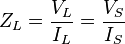 .
.
The apparent impedance  of this secondary circuit load referred to the primary winding circuit is governed by a squared turns ratio multiplication factor relationship derived as follows[6][7]
of this secondary circuit load referred to the primary winding circuit is governed by a squared turns ratio multiplication factor relationship derived as follows[6][7] .
.
Induction law[edit]
The transformer is based on two principles: first, that an electric current can produce a magnetic field and second that a changing magnetic field within a coil of wire induces a voltage across the ends of the coil (electromagnetic induction). Changing the current in the primary coil changes the magnetic flux that is developed. The changing magnetic flux induces a voltage in the secondary coil.
Referring to the two figures here, current passing through the primary coil creates a magnetic field. The primary and secondary coils are wrapped around a core of very high magnetic permeability, usually iron,[d] so that most of the magnetic flux passes through both the primary and secondary coils. Any secondary winding connected load causes current and voltage induction from primary to secondary circuits in indicated directions.
The voltage induced across the secondary coil may be calculated from Faraday's law of induction, which states that:

where Vs = Es is the instantaneous voltage, Ns is the number of turns in the secondary coil, and dΦ/dt is the derivative[e] of the magnetic flux Φ through one turn of the coil. If the turns of the coil are oriented perpendicularly to the magnetic field lines, the flux is the product of the magnetic flux density B and the area A through which it cuts. The area is constant, being equal to the cross-sectional area of the transformer core, whereas the magnetic field varies with time according to the excitation of the primary. Since the same magnetic flux passes through both the primary and secondary coils in an ideal transformer,[6] the instantaneous voltage across the primary winding equals

Taking the ratio of the above two equations gives the same voltage ratio and turns ratio relationship shown above, that is,
 .
.
The changing magnetic field induces an emf across each winding.[8] The primary emf, acting as it does in opposition to the primary voltage, is sometimes termed the counter emf.[9] This is in accordance with Lenz's law, which states that induction of emf always opposes development of any such change in magnetic field.
As still lossless and perfectly-coupled, the transformer still behaves as described above in the ideal transformer.
Polarity[edit]
A dot convention is often used in transformer circuit diagrams, nameplates or terminal markings to define the relative polarity of transformer windings. Positively-increasing instantaneous current entering the primary winding's dot end induces positive polarity voltage at the secondary winding's dot end.[10][11][12][f][g]
The real transformer[edit]
Real transformer deviations from ideal[edit]
The ideal model neglects the following basic linear aspects in real transformers:
- Core losses collectively called magnetizing current losses consisting of:[15]
- Hysteresis losses due to nonlinear application of the voltage applied in the transformer core
- Eddy current losses due to joule heating in core proportional to the square of the transformer's applied voltage.
- Whereas the ideal windings have no impedance, the windings in a real transformer have finite non-zero impedances in the form of:
- Joule losses due to resistance in the primary and secondary windings[15]
- Leakage flux that escapes from the core and passes through one winding only resulting in primary and secondary reactive impedance.
Leakage flux[edit]
Main article: Leakage inductance
The ideal transformer model assumes that all flux generated by the primary winding links all the turns of every winding, including itself. In practice, some flux traverses paths that take it outside the windings.[16] Such flux is termed leakage flux, and results in leakage inductance in series with the mutually coupled transformer windings.[9] Leakage flux results in energy being alternately stored in and discharged from the magnetic fields with each cycle of the power supply. It is not directly a power loss (see Stray losses below), but results in inferior voltage regulation, causing the secondary voltage to not be directly proportional to the primary voltage, particularly under heavy load.[16] Transformers are therefore normally designed to have very low leakage inductance. Nevertheless, it is impossible to eliminate all leakage flux because it plays an essential part in the operation of the transformer. The combined effect of the leakage flux and the electric field around the windings is what transfers energy from the primary to the secondary.[17]
In some applications increased leakage is desired, and long magnetic paths, air gaps, or magnetic bypass shunts may deliberately be introduced in a transformer design to limit the short-circuit current it will supply.[9] Leaky transformers may be used to supply loads that exhibit negative resistance, such as electric arcs, mercury vapor lamps, and neon signs or for safely handling loads that become periodically short-circuited such as electric arc welders.[18]
Air gaps are also used to keep a transformer from saturating, especially audio-frequency transformers in circuits that have a DC component flowing through the windings.[19]
Knowledge of leakage inductance is for example useful when transformers are operated in parallel. It can be shown that if the percent impedance (Z) and associated winding leakage reactance-to-resistance (X/R) ratio of two transformers were hypothetically exactly the same, the transformers would share power in proportion to their respective volt-ampere ratings (e.g. 500 kVA unit in parallel with 1,000 kVA unit, the larger unit would carry twice the current). However, the impedance tolerances of commercial transformers are significant. Also, the Z impedance and X/R ratio of different capacity transformers tends to vary, corresponding 1,000 kVA and 500 kVA units' values being, to illustrate, respectively, Z ~ 5.75%, X/R ~ 3.75 and Z ~ 5%, X/R ~ 4.75.[20][21]
Equivalent circuit[edit]
See also: Steinmetz equivalent circuit
Referring to the diagram, a practical transformer's physical behavior may be represented by an equivalent circuit model, which can incorporate an ideal transformer.[22]
Winding joule losses and leakage reactances are represented by the following series loop impedances of the model:
- Primary winding: RP, XP
- Secondary winding: RS, XS.
In normal course of circuit equivalence transformation, RS and XS are in practice usually referred to the primary side by multiplying these impedances by the turns ratio squared, (NP/NS) 2 = a2.

Core loss and reactance is represented by the following shunt leg impedances of the model:
- Core or iron losses: RC
- Magnetizing reactance: XM.
RC and XM are collectively termed themagnetizing branch of the model.
Core losses are caused mostly by hysteresis and eddy current effects in the core and are proportional to the square of the core flux for operation at a given frequency.[23] The finite permeability core requires a magnetizing current IM to maintain mutual flux in the core. Magnetizing current is in phase with the flux, the relationship between the two being non-linear due to saturation effects. However, all impedances of the equivalent circuit shown are by definition linear and such non-linearity effects are not typically reflected in transformer equivalent circuits.[23] With sinusoidal supply, core flux lags the induced emf by 90°. With open-circuited secondary winding, magnetizing branch current I0 equals transformer no-load current.[22]
The resulting model, though sometimes termed 'exact' equivalent circuit based on linearity assumptions, retains a number of approximations.[22] Analysis may be simplified by assuming that magnetizing branch impedance is relatively high and relocating the branch to the left of the primary impedances. This introduces error but allows combination of primary and referred secondary resistances and reactances by simple summation as two series impedances.
Transformer equivalent circuit impedance and transformer ratio parameters can be derived from the following tests: Open-circuit test,[h] short-circuit test, winding resistance test, and transformer ratio test.
Basic transformer parameters and construction[edit]
Effect of frequency[edit]
Transformer universal emf equation
If the flux in the core is purely sinusoidal, the relationship for either winding between its rmsvoltage Erms of the winding, and the supply frequencyf, number of turns N, core cross-sectional area a in m2and peak magnetic flux density Bpeak in Wb/m2 or T (tesla) is given by the universal emf equation:[15]

If the flux does not contain even harmonics the following equation can be used for half-cycle average voltage Eavg of any waveshape:

The time-derivative term in Faraday's Law shows that the flux in the core is theintegral with respect to time of the applied voltage.[25] Hypothetically an ideal transformer would work with direct-current excitation, with the core flux increasing linearly with time.[26] In practice, the flux rises to the point where magnetic saturation of the core occurs, causing a large increase in the magnetizing current and overheating the transformer. All practical transformers must therefore operate with alternating (or pulsed direct) current.[26]
The emf of a transformer at a given flux density increases with frequency.[15] By operating at higher frequencies, transformers can be physically more compact because a given core is able to transfer more power without reaching saturation and fewer turns are needed to achieve the same impedance. However, properties such as core loss and conductor skin effect also increase with frequency. Aircraft and military equipment employ 400 Hz power supplies which reduce core and winding weight.[27] Conversely, frequencies used for somerailway electrification systems were much lower (e.g. 16.7 Hz and 25 Hz) than normal utility frequencies (50 – 60 Hz) for historical reasons concerned mainly with the limitations of early electric traction motors. As such, the transformers used to step-down the high over-head line voltages (e.g. 15 kV) were much heavier for the same power rating than those designed only for the higher frequencies.
Operation of a transformer at its designed voltage but at a higher frequency than intended will lead to reduced magnetizing current. At a lower frequency, the magnetizing current will increase. Operation of a transformer at other than its design frequency may require assessment of voltages, losses, and cooling to establish if safe operation is practical. For example, transformers may need to be equipped with 'volts per hertz' over-excitation relays to protect the transformer from overvoltage at higher than rated frequency.
One example of state-of-the-art design is traction transformers used for electric multiple unit andhigh speed train service operating across the,country border and using different electrical standards, such transformers' being restricted to be positioned below the passenger compartment. The power supply to, and converter equipment being supply by, such traction transformers have to accommodate different input frequencies and voltage (ranging from as high as 50 Hz down to 16.7 Hz and rated up to 25 kV) while being suitable for multiple AC asynchronous motor and DC converters & motors with varying harmonics mitigation filtering requirements.
Large power transformers are vulnerable to insulation failure due to transient voltages with high-frequency components, such as caused in switching or by lightning.[28]
Energy losses[edit]
An ideal transformer would have no energy losses, and would be 100% efficient. In practical transformers, energy is dissipated in the windings, core, and surrounding structures. Larger transformers are generally more efficient, and those rated for electricity distribution usually perform better than 98%.[29]
Experimental transformers using superconducting windings achieve efficiencies of 99.85%.[30] The increase in efficiency can save considerable energy, and hence money, in a large heavily loaded transformer; the trade-off is in the additional initial and running cost of the superconducting design.
As transformer losses vary with load, it is often useful to express these losses in terms of no-load loss, full-load loss, half-load loss, and so on.Hysteresis and eddy current losses are constant at all loads and dominate overwhelmingly at no-load, variable winding joule losses dominating increasingly as load increases. The no-load loss can be significant, so that even an idle transformer constitutes a drain on the electrical supply and a running cost. Designing transformers for lower loss requires a larger core, good-quality silicon steel, or even amorphous steel for the core and thicker wire, increasing initial cost so that there is a trade-off between initial cost and running cost (also see energy efficient transformer).[31]
Transformer losses arise from:
- Winding joule losses
- Current flowing through winding conductors causes joule heating. As frequency increases, skin effect and proximity effect causes winding resistance and, hence, losses to increase.
- Core losses
-
- Hysteresis losses
- Each time the magnetic field is reversed, a small amount of energy is lost due to hysteresis within the core. According to Steinmetz's formula, the heat energy due to hysteresis is given by
 , and,
- hysteresis loss is thus given by
- where, f is the frequency, η is the hysteresis coefficient and βmax is the maximum flux density, the empirical exponent of which varies from about 1.4 to 1 .8 but is often given as 1.6 for iron.[31][32][33]
- Eddy current losses
- Ferromagnetic materials are also good conductors and a core made from such a material also constitutes a single short-circuited turn throughout its entire length. Eddy currents therefore circulate within the core in a plane normal to the flux, and are responsible forresistive heating of the core material. The eddy current loss is a complex function of the square of supply frequency and inverse square of the material thickness.[31] Eddy current losses can be reduced by making the core of a stack of plates electrically insulated from each other, rather than a solid block; all transformers operating at low frequencies use laminated or similar cores.

- Magnetostriction related transformer hum
- Magnetic flux in a ferromagnetic material, such as the core, causes it to physically expand and contract slightly with each cycle of the magnetic field, an effect known as magnetostriction, the frictional energy of which produces an audible noise known as mains hum ortransformer hum.[3][34] This transformer hum is especially objectionable in transformers supplied at power frequencies[i] and in high-frequency flyback transformers associated with PAL system CRTs.
- Stray losses
- Leakage inductance is by itself largely lossless, since energy supplied to its magnetic fields is returned to the supply with the next half-cycle. However, any leakage flux that intercepts nearby conductive materials such as the transformer's support structure will give rise to eddy currents and be converted to heat.[35] There are also radiative losses due to the oscillating magnetic field but these are usually small.
- Mechanical vibration and audible noise transmission
- In addition to magnetostriction, the alternating magnetic field causes fluctuating forces between the primary and secondary windings. This energy incites vibration transmission in interconnected metalwork, thus amplifying audible transformer hum.[36]
Core form and shell form transformers[edit]
Closed-core transformers are constructed in 'core form' or 'shell form'. When windings surround the core, the transformer is core form; when windings are surrounded by the core, the transformer is shell form. Shell form design may be more prevalent than core form design for distribution transformer applications due to the relative ease in stacking the core around winding coils.[37]Core form design tends to, as a general rule, be more economical, and therefore more prevalent, than shell form design for high voltage power transformer applications at the lower end of their voltage and power rating ranges (less than or equal to, nominally, 230 kV or 75 MVA). At higher voltage and power ratings, shell form transformers tend to be more prevalent.[37][38][39][40] Shell form design tends to be preferred for extra high voltage and higher MVA applications because, though more labor intensive to manufacture, shell form transformers are characterized as having inherently better kVA-to-weight ratio, better short-circuit strength characteristics and higher immunity to transit damage.[40]
Construction[edit]
Cores[edit]
Laminated steel cores[edit]
Transformers for use at power or audio frequencies typically have cores made of high permeability silicon steel.[41] The steel has a permeability many times that of free space and the core thus serves to greatly reduce the magnetizing current and confine the flux to a path which closely couples the windings.[42] Early transformer developers soon realized that cores constructed from solid iron resulted in prohibitive eddy current losses, and their designs mitigated this effect with cores consisting of bundles of insulated iron wires.[43] Later designs constructed the core by stacking layers of thin steel laminations, a principle that has remained in use. Each lamination is insulated from its neighbors by a thin non-conducting layer of insulation.[44] The universal transformer equation indicates a minimum cross-sectional area for the core to avoid saturation.
The effect of laminations is to confine eddy currents to highly elliptical paths that enclose little flux, and so reduce their magnitude. Thinner laminations reduce losses,[45] but are more laborious and expensive to construct.[46] Thin laminations are generally used on high-frequency transformers, with some of very thin steel laminations able to operate up to 10 kHz.

One common design of laminated core is made from interleaved stacks of E-shaped steel sheets capped with I-shaped pieces, leading to its name of 'E-I transformer'.[46]Such a design tends to exhibit more losses, but is very economical to manufacture. The cut-core or C-core type is made by winding a steel strip around a rectangular form and then bonding the layers together. It is then cut in two, forming two C shapes, and the core assembled by binding the two C halves together with a steel strap.[46] They have the advantage that the flux is always oriented parallel to the metal grains, reducing reluctance.
A steel core's remanence means that it retains a static magnetic field when power is removed. When power is then reapplied, the residual field will cause a high inrush currentuntil the effect of the remaining magnetism is reduced, usually after a few cycles of the applied AC waveform.[47] Overcurrent protection devices such as fuses must be selected to allow this harmless inrush to pass. On transformers connected to long, overhead power transmission lines, induced currents due to geomagnetic disturbances duringsolar storms can cause saturation of the core and operation of transformer protection devices.[48]
Distribution transformers can achieve low no-load losses by using cores made with low-loss high-permeability silicon steel or amorphous (non-crystalline) metal alloy. The higher initial cost of the core material is offset over the life of the transformer by its lower losses at light load.[49]
Solid cores[edit]
Powdered iron cores are used in circuits such as switch-mode power supplies that operate above mains frequencies and up to a few tens of kilohertz. These materials combine high magnetic permeability with high bulk electrical resistivity. For frequencies extending beyond the VHF band, cores made from non-conductive magnetic ceramic materials called ferrites are common.[46] Some radio-frequency transformers also have movable cores (sometimes called 'slugs') which allow adjustment of the coupling coefficient (and bandwidth) of tuned radio-frequency circuits.
Toroidal cores[edit]
Toroidal transformers are built around a ring-shaped core, which, depending on operating frequency, is made from a long strip of silicon steel or permalloy wound into a coil, powdered iron, or ferrite.[50] A strip construction ensures that the grain boundaries are optimally aligned, improving the transformer's efficiency by reducing the core's reluctance. The closed ring shape eliminates air gaps inherent in the construction of an E-I core.[18] The cross-section of the ring is usually square or rectangular, but more expensive cores with circular cross-sections are also available. The primary and secondary coils are often wound concentrically to cover the entire surface of the core. This minimizes the length of wire needed, and also provides screening to minimize the core's magnetic field from generating electromagnetic interference.
Toroidal transformers are more efficient than the cheaper laminated E-I types for a similar power level. Other advantages compared to E-I types, include smaller size (about half), lower weight (about half), less mechanical hum (making them superior in audio amplifiers), lower exterior magnetic field (about one tenth), low off-load losses (making them more efficient in standby circuits), single-bolt mounting, and greater choice of shapes. The main disadvantages are higher cost and limited power capacity (seeClassification parameters below). Because of the lack of a residual gap in the magnetic path, toroidal transformers also tend to exhibit higher inrush current, compared to laminated E-I types.
Ferrite toroidal cores are used at higher frequencies, typically between a few tens of kilohertz to hundreds of megahertz, to reduce losses, physical size, and weight of inductive components. A drawback of toroidal transformer construction is the higher labor cost of winding. This is because it is necessary to pass the entire length of a coil winding through the core aperture each time a single turn is added to the coil. As a consequence, toroidal transformers rated more than a few kVA are uncommon. Small distribution transformers may achieve some of the benefits of a toroidal core by splitting it and forcing it open, then inserting a bobbin containing primary and secondary windings.
Air cores[edit]
A physical core is not an absolute requisite and a functioning transformer can be produced simply by placing the windings near each other, an arrangement termed an 'air-core' transformer. The air which comprises the magnetic circuit is essentially lossless, and so an air-core transformer eliminates loss due to hysteresis in the core material.[9] The leakage inductance is inevitably high, resulting in very poor regulation, and so such designs are unsuitable for use in power distribution.[9] They have however very high bandwidth, and are frequently employed in radio-frequency applications,[51] for which a satisfactory coupling coefficient is maintained by carefully overlapping the primary and secondary windings. They're also used for resonant transformers such as Tesla coils where they can achieve reasonably low loss in spite of the high leakage inductance.
Windings[edit]
Main article: Windings
The conducting material used for the windings depends upon the application, but in all cases the individual turns must be electrically insulated from each other to ensure that the current travels throughout every turn.[52] For small power and signal transformers, in which currents are low and the potential difference between adjacent turns is small, the coils are often wound from enamelled magnet wire, such as Formvar wire. Larger power transformers operating at high voltages may be wound with copper rectangular strip conductors insulated by oil-impregnated paper and blocks of pressboard.[53]
High-frequency transformers operating in the tens to hundreds of kilohertz often have windings made of braided Litz wireto minimize the skin-effect and proximity effect losses.[25] Large power transformers use multiple-stranded conductors as well, since even at low power frequencies non-uniform distribution of current would otherwise exist in high-current windings.[53] Each strand is individually insulated, and the strands are arranged so that at certain points in the winding, or throughout the whole winding, each portion occupies different relative positions in the complete conductor. The transposition equalizes the current flowing in each strand of the conductor, and reduces eddy current losses in the winding itself. The stranded conductor is also more flexible than a solid conductor of similar size, aiding manufacture.[53]
The windings of signal transformers minimize leakage inductance and stray capacitance to improve high-frequency response. Coils are split into sections, and those sections interleaved between the sections of the other winding.
Power-frequency transformers may have taps at intermediate points on the winding, usually on the higher voltage winding side, for voltage adjustment. Taps may be manually reconnected, or a manual or automatic switch may be provided for changing taps. Automatic on-load tap changers are used in electric power transmission or distribution, on equipment such as arc furnace transformers, or for automatic voltage regulators for sensitive loads. Audio-frequency transformers, used for the distribution of audio to public address loudspeakers, have taps to allow adjustment of impedance to each speaker. A center-tapped transformer is often used in the output stage of an audio power amplifier in a push-pull circuit. Modulation transformers in AM transmitters are very similar.
Dry-type transformer winding insulation systems can be either of standard open-wound 'dip-and-bake' construction or of higher quality designs that include vacuum pressure impregnation (VPI), vacuum pressure encapsulation (VPE), and cast coil encapsulation processes.[54] In the VPI process, a combination of heat, vacuum and pressure is used to thoroughly seal, bind, and eliminate entrained air voids in the winding polyester resin insulation coat layer, thus increasing resistance to corona. VPE windings are similar to VPI windings but provide more protection against environmental effects, such as from water, dirt or corrosive ambients, by multiple dips including typically in terms of final epoxy coat.[55]
Cooling[edit]
See also: Arrhenius equation
To place the cooling problem in perspective, the accepted rule of thumb is that the life expectancy of insulation in all electric machines including all transformers is halved for about every 7°C to 10°C increase in operating temperature, this life expectancy halving rule holding more narrowly when the increase is between about 7°C to 8°C in the case of transformer winding cellulose insulation.[56][57][58]
Small dry-type and liquid-immersed transformers are often self-cooled by natural convection andradiation heat dissipation. As power ratings increase, transformers are often cooled by forced-air cooling, forced-oil cooling, water-cooling, or combinations of these.[59] Large transformers are filled withtransformer oil that both cools and insulates the windings.[60] Transformer oil is a highly refined mineral oilthat cools the windings and insulation by circulating within the transformer tank. The mineral oil and paperinsulation system has been extensively studied and used for more than 100 years. It is estimated that 50% of power transformers will survive 50 years of use, that the average age of failure of power transformers is about 10 to 15 years, and that about 30% of power transformer failures are due to insulation and overloading failures.[61][62] Prolonged operation at elevated temperature degrades insulating properties of winding insulation and dielectric coolant, which not only shortens transformer life but can ultimately lead to catastrophic transformer failure.[56] With a great body of empirical study as a guide, transformer oil testing including dissolved gas analysis provides valuable maintenance information. This can translate in a need to monitor, model, forecast and manage oil and winding conductor insulation temperature conditions under varying, possibly difficult, power loading conditions.[63][64]
Building regulations in many jurisdictions require indoor liquid-filled transformers to either use dielectric fluids that are less flammable than oil, or be installed in fire-resistant rooms.[65] Air-cooled dry transformers can be more economical where they eliminate the cost of a fire-resistant transformer room.
The tank of liquid filled transformers often has radiators through which the liquid coolant circulates by natural convection or fins. Some large transformers employ electric fans for forced-air cooling, pumps for forced-liquid cooling, or have heat exchangers for water-cooling.[60] An oil-immersed transformer may be equipped with a Buchholz relay, which, depending on severity of gas accumulation due to internal arcing, is used to either alarm or de-energize the transformer.[47] Oil-immersed transformer installations usually include fire protection measures such as walls, oil containment, and fire-suppression sprinkler systems. Another protection means consists infast depressurization systems which are activated by the first dynamic pressure peak of the shock wave, avoiding transformer explosion before static pressure increases. Many explosions are reported to have been avoided thanks to this technology.[66]
Polychlorinated biphenyls have properties that once favored their use as a dielectric coolant, though concerns over their environmental persistence led to a widespread ban on their use.[67] Today, non-toxic, stable silicone-based oils, or fluorinated hydrocarbons may be used where the expense of a fire-resistant liquid offsets additional building cost for a transformer vault.[65][68] PCBs for new equipment was banned in 1981 and in 2000 for use in existing equipment in United Kingdom[69] Legislation enacted in Canada between 1977 and 1985 essentially bans PCB use in transformers manufactured in or imported into the country after 1980, the maximum allowable level of PCB contamination in existing mineral oil transformers being 50 ppm.[70]
Some transformers, instead of being liquid-filled, have their windings enclosed in sealed, pressurized tanks and cooled by nitrogen or sulfur hexafluoride gas.[68]
Experimental power transformers in the 500-to-1,000 kVA range have been built with liquid nitrogen or helium cooled superconductingwindings, which, compared to usual transformer losses, eliminates winding losses without affecting core losses.[71][72]
Insulation drying[edit]
Construction of oil-filled transformers requires that the insulation covering the windings be thoroughly dried of residual moisture before the oil is introduced. Drying is carried out at the factory, and may also be required as a field service. Drying may be done by circulating hot air around the core, or by vapor-phase drying (VPD) where an evaporated solvent transfers heat by condensation on the coil and core.
For small transformers, resistance heating by injection of current into the windings is used. The heating can be controlled very well, and it is energy efficient. The method is called low-frequency heating (LFH) since the current is injected at a much lower frequency than the nominal of the power grid, which is normally 50 or 60 Hz. A lower frequency reduces the effect of the inductance in the transformer, so the voltage needed to induce the current can be reduced.[73] The LFH drying method is also used for service of older transformers.[74]
Bushings[edit]
Larger transformers are provided with high-voltage insulated bushings made of polymers or porcelain. A large bushing can be a complex structure since it must provide careful control of the electric field gradient without letting the transformer leak oil.[75]
No comments:
Post a Comment