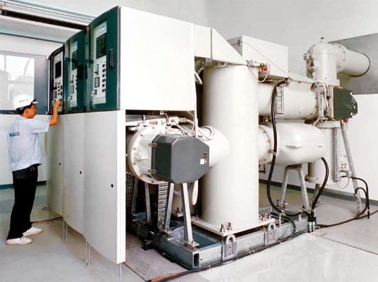
ABB Gas-insulated Switchgear ELK-04 Modular System up to 170 kV, 4000 A, 63 kA
Continued from first part: Erection procedure for HV switchgear (Part 1)
Positioning of cubicles
Positioning of the cubicles should start near to the centre of the switchboard, installing as early as possible the enclosures associated with any special chambers or trunking.
The first enclosure should be positioned and checked to ensure the side sheets are plumb and that any runner rails are level in both planes.
When the first enclosure panel is correctly set the remaining enclosures should be positioned successively on alternate sides of this panel to make the front form an unbroken line.
Adjacent enclosures should be bolted together after they have been correctly aligned using whatever shimming proves necessary to make sure that the cubicles are vertically and horizontally true. The fixing bolts should be positioned in the foundation holes andcemented in leaving adequate time for the cement to set before tightening up.
The equipment may now be connected up and cable joints made.
In particular one must confirm that the earthing of the equipment has been carried out using the recommended cross-section of material and satisfactory terminations.
The LV system must then be proved for continuity, preferably by using a hand generator or other portable device and with a current of about 1.5 times the design current. A further examination of all incoming and outgoing circuit and auxiliary cables, including a test of the correctness of the connections at the remote ends, should be done; this should include measuring the insulation resistance and continuity of all cables and wiring including internal and auxiliary connections.
Where appropriate, phase rotation checks must be made before three-phase drives are energised.
All moving parts must be inspected to ensure they are all operative.
Dashpots must be filled to the correct level with the right grade of fluid, and the operation and accuracy of meters and relays by secondary or primary injection tests should be checked. All settings should be agreed with the client’s engineers.

Gas-insulated switchgear ELK-04 with integrated control cabinets
All cable boxes must be properly topped up and compound filling spouts capped off. All insulators and spouts must be clean and dry and cover plates securely bolted up with all screws in position and tightened and breather vents clear of obstruction. Ensure that the top of the equipment is free from all dirt and rubbish.
A final check on all incoming and outgoing cable connections to terminals ensures that they are tight and have adequate clearance. High-voltage testing can then be carried out to the test figures laid down in the appropriate switchgear specification or as specified by the client’s engineers who should witness the tests and sign the test results.
After testing, precautions must be taken to discharge any static and remove the test connections before bolting up any covers removed for testing.
Before energising, the operation of all circuit-breakers and relays should be confirmed manually and electrically to ensure that no sticking or malfunction is present, particular attention being given to manual trip and close operations and to the operation of overcurrent relays and residual current devices.
When the equipment is ready to make alive all circuits not in service shall be locked off at each end and safety operation procedures adopted. All switching operations should be carried out by a competent person.
The substation’s entry and emergency exist doors must be operative and kept clear and free from obstruction. All substations should be kept locked when the equipment is live, and access restricted to authorised personnel only.
Danger, safety, shock cards and any statutory notices must be prominently displayed.
Tools required for operating switchgear should be stored adjacent to the equipment in proper racks or cabinets. Circuit and interlock keys should also be contained in special cabinets under the control of authorised personnel and no spare keys must be allowed to abort the safety of the system. Batteries should be examined to ensure that they have received their first charge and the electrolyte is at the correct level and of appropriate specific gravity.
The fire-fighting requirement should be checked and if it is CO2 it must be confirmed that the safety lock-off procedure is understood by the personnel authorised to enter the substation.
External warning notices must be fixed to protect any strangers from inadvertently suffocating.
Prefabricated gas-insulated switchgear (GIS)
Integrated GIS is a prefabricated gas-insulated switchgear (GIS) unit with housing is based on ABB’s well-proven GIS technology and can be produced at the same speed as a conventional GIS but has a considerably shorter installation time which is less than 50 percent of typical GIS installations.
Cant see this video? Click here to watch it on Youtube.
Resource: Handbook of Electrical Installation Practice – Eur Ing Geoffrey Stokes (Get it from Amazon)

No comments:
Post a Comment