
Power factor
From Wikipedia, the free encyclopedia
For other uses, see Power factor (pistol).
The power factor of an AC electrical power system is defined as the ratio of the real power flowing to the load, to the apparent power in the circuit,[1][2] and is a dimensionless number between -1 and 1. Real power is the capacity of the circuit for performing work in a particular time. Apparent power is the product of the current and voltage of the circuit. Due to energy stored in the load and returned to the source, or due to a non-linear load that distorts the wave shape of the current drawn from the source, the apparent power will be greater than the real power. A negative power factor occurs when the device which is normally the load generates power which then flows back towards the device which is normally considered the generator.[3][4][5]
In an electric power system, a load with a low power factor draws more current than a load with a high power factor for the same amount of useful power transferred. The higher currents increase the energy lost in the distribution system, and require larger wires and other equipment. Because of the costs of larger equipment and wasted energy, electrical utilities will usually charge a higher cost to industrial or commercial customers where there is a low power factor.
Linear loads with low power factor (such as induction motors) can be corrected with a passive network ofcapacitors or inductors. Non-linear loads, such as rectifiers, distort the current drawn from the system. In such cases, active or passive power factor correction may be used to counteract the distortion and raise the power factor. The devices for correction of the power factor may be at a central substation, spread out over a distribution system, or built into power-consuming equipment.
Contents
[hide]Linear circuits

 ,
,  ). The blue line shows all the power is stored temporarily in the load during the first quarter cycle and returned to the grid during the second quarter cycle, so no real power is consumed.
 ,
,  ). The blue line shows some of the power is returned to the grid during the part of the cycle labelled φ
In a purely resistive AC circuit, voltage and current waveforms are in step (or in phase), changing polarity at the same instant in each cycle. All the power entering the load is consumed (or dissipated). Where reactive loads are present, such as with capacitors or inductors, energy storage in the loads results in a time difference between the current and voltage waveforms. During each cycle of the AC voltage, extra energy, in addition to any energy consumed in the load, is temporarily stored in the load in electric or magnetic fields, and then returned to the power grid a fraction of a second later in the cycle. The "ebb and flow" of this nonproductive power increases the current in the line. Thus, a circuit with a low power factor will use higher currents to transfer a given quantity of real power than a circuit with a high power factor. A linear load does not change the shape of the waveform of the current, but may change the relative timing (phase) between voltage and current.
Circuits containing purely resistive heating elements (filament lamps, cooking stoves, etc.) have a power factor of 1.0. Circuits containing inductive or capacitive elements (electric motors,solenoid valves, lamp ballasts, and others ) often have a power factor below 1.0.
Definition and calculation
AC power flow has the three components: real power (also known as active power) (P), measured in watts (W); apparent power (S), measured in volt-amperes (VA); and reactive power (Q), measured in reactive volt-amperes (var).[6]
The power factor is defined as:
 .
.
In the case of a perfectly sinusoidal waveform, P, Q and S can be expressed as vectors that form a vector triangle such that:

If  is the phase angle between the current and voltage, then the power factor is equal to the cosine of the angle,
  , and:
is the phase angle between the current and voltage, then the power factor is equal to the cosine of the angle, , and:
Since the units are consistent, the power factor is by definition a dimensionless number between -1 and 1. When power factor is equal to 0, the energy flow is entirely reactive, and stored energy in the load returns to the source on each cycle. When the power factor is 1, all the energy supplied by the source is consumed by the load. Power factors are usually stated as "leading" or "lagging" to show the sign of the phase angle. Capacitive loads are leading (current leads voltage), and inductive loads are lagging (current lags voltage).
If a purely resistive load is connected to a power supply, current and voltage will change polarity in step, the power factor will be unity (1), and the electrical energy flows in a single direction across the network in each cycle. Inductive loads such as transformers and motors (any type of wound coil) consume reactive power with current waveform lagging the voltage. Capacitive loads such as capacitor banks or buried cable generate reactive power with current phase leading the voltage. Both types of loads will absorb energy during part of the AC cycle, which is stored in the device's magnetic or electric field, only to return this energy back to the source during the rest of the cycle.
For example, to get 1 kW of real power, if the power factor is unity, 1 kVA of apparent power needs to be transferred (1 kW ÷ 1 = 1 kVA). At low values of power factor, more apparent power needs to be transferred to get the same real power. To get 1 kW of real power at 0.2 power factor, 5 kVA of apparent power needs to be transferred (1 kW ÷ 0.2 = 5 kVA). This apparent power must be produced and transmitted to the load in the conventional fashion, and is subject to the usual distributed losses in the production and transmission processes.
Electrical loads consuming alternating current power consume both real power and reactive power. The vector sum of real and reactive power is the apparent power. The presence of reactive power causes the real power to be less than the apparent power, and so, the electric load has a power factor of less than 1.
Power factor correction of linear loads
A high power factor is generally desirable in a transmission system to reduce transmission losses and improve voltage regulation at the load. It is often desirable to adjust the power factor of a system to near 1.0. When reactive elements supply or absorb reactive power near the load, the apparent power is reduced. Power factor correction may be applied by an electric power transmission utility to improve the stability and efficiency of the transmission network. Individual electrical customers who are charged by their utility for low power factor may install correction equipment to reduce those costs.
Power factor correction brings the power factor of an AC power circuit closer to 1 by supplying reactive power of opposite sign, adding capacitors or inductors that act to cancel the inductive or capacitive effects of the load, respectively. For example, the inductive effect of motor loads may be offset by locally connected capacitors. If a load had a capacitive value, inductors (also known as reactors in this context) are connected to correct the power factor. In the electricity industry, inductors are said to consume reactive power and capacitors are said tosupply it, even though the energy is just moving back and forth on each AC cycle.
The reactive elements can create voltage fluctuations and harmonic noise when switched on or off. They will supply or sink reactive power regardless of whether there is a corresponding load operating nearby, increasing the system's no-load losses. In the worst case, reactive elements can interact with the system and with each other to create resonant conditions, resulting in system instability and severe overvoltage fluctuations. As such, reactive elements cannot simply be applied without engineering analysis.

An automatic power factor correction unit consists of a number of capacitors that are switched by means of contactors. These contactors are controlled by a regulator that measures power factor in an electrical network. Depending on the load and power factor of the network, the power factor controller will switch the necessary blocks of capacitors in steps to make sure the power factor stays above a selected value.
Instead of using a set of switched capacitors, an unloadedsynchronous motor can supply reactive power. The reactive power drawn by the synchronous motor is a function of its field excitation. This is referred to as a synchronous condenser. It is started and connected to the electrical network. It operates at a leading power factor and puts vars onto the network as required to support a system’s voltage or to maintain the system power factor at a specified level.
The condenser’s installation and operation are identical to largeelectric motors. Its principal advantage is the ease with which the amount of correction can be adjusted; it behaves like an electrically variable capacitor. Unlike capacitors, the amount of reactive power supplied is proportional to voltage, not the square of voltage; this improves voltage stability on large networks. Synchronous condensors are often used in connection with high-voltage direct-current transmission projects or in large industrial plants such as steel mills.
For power factor correction of high-voltage power systems or large, fluctuating industrial loads, power electronic devices such as the Static VAR compensator or STATCOM are increasingly used. These systems are able to compensate sudden changes of power factor much more rapidly than contactor-switched capacitor banks, and being solid-state require less maintenance than synchronous condensers.
Caution - While using capacitors for power factor correction in industrial application, capacitor charging must be connected to main switch. This will aid charging of capacitor while the induction load is switched on and charging of capacitor is cut off on switching off mains. If the capacitor is in charged condition after the induction load is cut off, electronic energy meter reading will malfunction and show incorrect values resulting in excessive-wrong consumption charge.
Non-linear loads
A non-linear load on a power system is typically a rectifier (such as used in a power supply), or some kind of arc discharge device such as a fluorescent lamp, electric welding machine, or arc furnace. Because current in these systems is interrupted by a switching action, the current contains frequency components that are multiples of the power system frequency. Distortion power factor is a measure of how much the harmonic distortion of a load current decreases the average power transferred to the load.

Non-sinusoidal components
Non-linear loads change the shape of the current waveform from a sine wave to some other form. Non-linear loads create harmonic currents in addition to the original (fundamental frequency) AC current. Filters consisting of linear capacitors and inductors can prevent harmonic currents from entering the supplying system.
In linear circuits having only sinusoidal currents and voltages of one frequency, the power factor arises only from the difference in phase between the current and voltage. This is "displacement power factor". The concept can be generalized to a total, distortion, or true power factor where the apparent power includes all harmonic components. This is of importance in practical power systems that containnon-linear loads such as rectifiers, some forms of electric lighting, electric arc furnaces, welding equipment, switched-mode power supplies and other devices.
A typical multimeter will give incorrect results when attempting to measure the AC current drawn by a non-sinusoidal load; the instruments sense the average value of a rectified waveform. The average response is then calibrated to the effective, RMS value. An RMS sensing multimeter must be used to measure the actual RMS currents and voltages (and therefore apparent power). To measure the real power or reactive power, a watt meter designed to work properly with non-sinusoidal currents must be used.
Distortion power factor
The distortion power factor describes how the harmonic distortion of a load current decreases the average power transferred to the load.
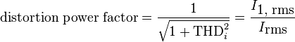
 is the total harmonic distortion of the load current. This definition assumes that the voltage stays undistorted (sinusoidal, without harmonics). This simplification is often a good approximation in practice.
  is the fundamental component of the current and
  is the total current - both are root mean square-values.
The result when multiplied with the displacement power factor (DPF) is the overall, true power factor or just power factor (PF):

Switched-mode power supplies
Main article: switched-mode power supply#Power factor
A particularly important class of non-linear loads is the millions of personal computers that typically incorporateswitched-mode power supplies (SMPS) with rated output power ranging from a few watts to more than 1 kW. Historically, these very-low-cost power supplies incorporated a simple full-wave rectifier that conducted only when the mains instantaneous voltage exceeded the voltage on the input capacitors. This leads to very highratios of peak-to-average input current, which also lead to a low distortion power factor and potentially serious phase and neutral loading concerns.
A typical switched-mode power supply first makes a DC bus, using a bridge rectifier or similar circuit. The output voltage is then derived from this DC bus. The problem with this is that the rectifier is a non-linear device, so the input current is highly non-linear. That means that the input current has energy at harmonics of the frequency of the voltage.
This presents a particular problem for the power companies, because they cannot compensate for the harmonic current by adding simple capacitors or inductors, as they could for the reactive power drawn by a linear load. Many jurisdictions are beginning to legally require power factor correction for all power supplies above a certain power level.
Regulatory agencies such as the EU have set harmonic limits as a method of improving power factor. Declining component cost has hastened implementation of two different methods. To comply with current EU standard EN61000-3-2, all switched-mode power supplies with output power more than 75 W must include passive power factor correction, at least. 80 Plus power supply certification requires a power factor of 0.9 or more.[7]
Power factor correction in non-linear loads
Passive PFC
The simplest way to control the harmonic current is to use a filter: it is possible to design a filter that passes current only at line frequency (50 or 60 Hz). This filter reduces the harmonic current, which means that the non-linear device now looks like a linear load. At this point the power factor can be brought to near unity, using capacitors or inductors as required. This filter requires large-value high-current inductors, however, which are bulky and expensive.
This is a simple way of correcting the nonlinearity of a load by using capacitor banks. It is not as effective as active PFC.[10][11][12][13][14] One example of this is a valley-fill circuit.
Passive PFCs are typically more power efficient than active PFCs. Efficiency is not to be confused with the PFC, though many computer hardware reviews conflate them.[10] A passive PFC on a switching computer PSU has a typical power efficiency of around 96%, while an active PFC has a typical efficiency of about 94%.[15]
Active PFC
An "active power factor corrector" (active PFC) is a power electronic system that changes the waveshape of current drawn by a load to improve the power factor. The purpose is to make the load circuitry that is power factor corrected appear purely resistive (apparent power equal to real power).[16] In this case, the voltage and current are in phase and the reactive power consumption is zero. This enables the most efficient delivery of electrical power from the power company to the consumer.[17]

Some types of active PFC are:
Active power factor correctors can be single-stage or multi-stage.
In the case of a switched-mode power supply, a boost converter is inserted between the bridge rectifier and the main input capacitors. The boost converter attempts to maintain a constant DC bus voltage on its output while drawing a current that is always in phase with and at the same frequency as the line voltage. Another switchmode converter inside the power supply produces the desired output voltage from the DC bus. This approach requires additional semiconductor switches and control electronics, but permits cheaper and smaller passive components. It is frequently used in practice. For example, SMPS with passive PFC can achieve power factor of about 0.7–0.75, SMPS with active PFC, up to 0.99 power factor, while a SMPS without any power factor correction has a power factor of only about 0.55–0.65.[18]
Due to their very wide input voltage range, many power supplies with active PFC can automatically adjust to operate on AC power from about 100 V (Japan) to 230 V (Europe). That feature is particularly welcome in power supplies for laptops.
Importance of power factor in distribution systems

Power factors below 1.0 require a utility to generate more than the minimum volt-amperes necessary to supply the real power (watts). This increases generation and transmission costs. For example, if the load power factor were as low as 0.7, the apparent power would be 1.4 times the real power used by the load. Line current in the circuit would also be 1.4 times the current required at 1.0 power factor, so the losses in the circuit would be doubled (since they are proportional to the square of the current). Alternatively all components of the system such as generators, conductors, transformers, and switchgear would be increased in size (and cost) to carry the extra current.
Utilities typically charge additional costs to commercial customers who have a power factor below some limit, which is typically 0.9 to 0.95. Engineers are often interested in the power factor of a load as one of the factors that affect the efficiency of power transmission.
With the rising cost of energy and concerns over the efficient delivery of power, active PFC has become more common in consumer electronics.[19] Current Energy Star guidelines for computers (ENERGY STAR Program Requirements for Computers Version 5.0) call for a power factor of ≥ 0.9 at 100% of rated output in the PC's power supply. According to a white paper authored by Intel and the U.S. Environmental Protection Agency, PCs with internal power supplies will require the use of active power factor correction to meet the ENERGY STAR 5.0 Program Requirements for Computers.[20]
In Europe, IEC 555-2 requires power factor correction be incorporated into consumer products.[21]
Measuring the power factor
The power factor in a single-phase circuit (or balanced three-phase circuit) can be measured with the wattmeter-ammeter-voltmeter method, where the power in watts is divided by the product of measured voltage and current. The power factor of a balanced polyphase circuit is the same as that of any phase. The power factor of an unbalanced polyphase circuit is not uniquely defined.
A direct reading power factor meter can be made with a moving coil meter of the electrodynamic type, carrying two perpendicular coils on the moving part of the instrument. The field of the instrument is energized by the circuit current flow. The two moving coils, A and B, are connected in parallel with the circuit load. One coil, A, will be connected through a resistor and the second coil, B, through an inductor, so that the current in coil B is delayed with respect to current in A. At unity power factor, the current in A is in phase with the circuit current, and coil A provides maximum torque, driving the instrument pointer toward the 1.0 mark on the scale. At zero power factor, the current in coil B is in phase with circuit current, and coil B provides torque to drive the pointer towards 0. At intermediate values of power factor, the torques provided by the two coils add and the pointer takes up intermediate positions.[22]
Another electromechanical instrument is the polarized-vane type.[23] In this instrument a stationary field coil produces a rotating magnetic field, just like a polyphase motor. The field coils are connected either directly to polyphase voltage sources or to a phase-shifting reactor if a single-phase application. A second stationary field coil, perpendicular to the voltage coils, carries a current proportional to current in one phase of the circuit. The moving system of the instrument consists of two vanes that are magnetized by the current coil. In operation the moving vanes take up a physical angle equivalent to the electrical angle between the voltage source and the current source. This type of instrument can be made to register for currents in both directions, giving a four-quadrant display of power factor or phase angle.
Digital instruments can be made that either directly measure the time lag between voltage and current waveforms and so calculate the power factor, or by measuring both true and apparent power in the circuit and calculating the quotient. The first method is only accurate if voltage and current are sinusoidal; loads such as rectifiers distort the waveforms from the sinusoidal shape.
Mnemonics
English-language power engineering students are advised to remember: "ELI the ICE man" or "ELI on ICE" – the voltage E leads the current I in an inductor L; the current leads the voltage in a capacitor C.
Another common mnemonic is CIVIL – in a capacitor (C) the current (I) leads voltage (V), voltage (V) leads current (I) in an inductor (L).
FOR YOUR PHILIPPINE ELECTRICAL CONCERNS...NEEDS...INSTALLATION...QUOTATION...ORDERS
KINDLY EMAIL US: SAFEELECTRICAL2013@GMAIL.COM
FOR YOUR PHILIPPINE ELECTRICAL CONCERNS...NEEDS...INSTALLATION...QUOTATION...ORDERS:
KINDLY EMAIL US: SAFEELECTRICAL2013@GMAIL.COM
2 comments:
Nice Blog About Power Factor Control Panel!! We manufacture and supply superior quality and various kinds of Power Factor Control Panel
1st Player 80 Plus Power Supply in UAE, Full Modular Power Supply in UAE, ATX Power Supply in UAE
https://pcdubai.com/1st-player-80-plus/
1st Player 80 Plus PSU in UAE, Safe Shopping Multiple Payment Options Express Delivery PC Dubai Moneyback Guarantee.
1632896773346-10
Post a Comment