
In the following article, i explain the principles of operation of a brushed DC motor with permanent magnets. Also i show how a DC motor (with permanent magnets) is made and what is inside in such a motor. If you are interested in brushless DC motors, then better go to the page about how brushless DC motors work.
The Ampere's rule (the right-hand screw rule)
It is Frenchman Andre-Marie Ampere (1775–1836), a mathematician and physicist, who discovered what happens to a wire winded in a coil when current flows within. The current will generate a magnetic field around the coil, as shown in the following drawing:
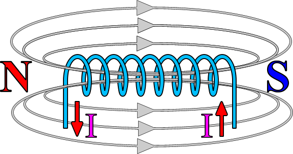

The "right-hand screw rule"
Using your right hand, you can find out the direction of the magnetic lines as well as the North pole orientation. Close your fist and hold your thumb upwards, like thumbs-up. If you had the coil inside your hand and your fingers (except the thumb) was showing the direction of the current, then the thumb shows the direction of the magnetic lines as well as the orientation of the North pole. This is called "the right-hand screw rule".
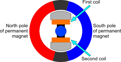
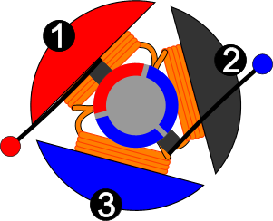
The basic DC motor has actually two windings and two permanent magnets. The coils are powered from the commutator and the brushes. We will see these two later on. For now, you only need to know that during a full cycle of the rotor, the current that runs through each winding change direction once. Thus, each electromagnet will change its magnetic polarity. Moreover, the windings of the two magnets are winded in reversed direction. Thus, when one electromagnet is North, the other is South and vice versa. Look at the following drawing of the basic DC motor:
The following animation indicates how the two electromagnets changes magnetic polarity during a full rotation:

I have with RED color the North pole and with BLUE the South pole. If you watch this animation, you will see that there is one moment that both electromagnets are turned off. This is the time that the basic DC motor provides no torque at all. In all other occasions, the magnets are either PULLED from the opposite pole or PUSHED from the same pole and therefore the mechanical power is generated.
The commutator and the brushes of a DC motor
This kind of DC motor is called "Brushed DC motor". Why? Because it uses brushes... The brushes are the way that the motor provides the coils with power, and the geometrical characteristics and position of the brushes (and the commutator of course) will be responsible for changing the magnetic field of the two electromagnets according to the position of the rotor. So, how this is done? The brushes are two metallic pieces that act like springs. On one side, they have a piece of conductive material, usually made of carbon to stand against friction. On the other side, they have the pin that the power supply is applied to the motor. The brushes are pushed (by the spring action of the metallic part) against the commutator. The commutator is a metallic ring, also conductive and able to stand friction, that is divided in two parts. The following drawing explains how these parts are:
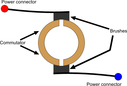
The commutator is fixed on the shaft of the motor. Each semi-ring has one pole of each coil. Giving thus power to both half-rings, is like giving power to the coils. But while the shaft of the motor rotates, the commutator rotates as well. This causes the poles of the power supply provided to the coils to change. This change of the electric poles, has an affect on the magnetic poles as well. The current direction is changed and - due to the rule of the right-hand screw - the poles of the electromagnets will also change. The following two animations indicates this procedure. The left one shows the brushes and the commutator from above, while the right one shows how the electric and magnetic polarity is changed.
 |  |
Notice how each part of the commutator changes polarity as it rotates. This is the basic operation of the DC motor. Notice also, that there is one moment that the commutator is short-circuited. During this time, the motor produces no power at all, and also the short-circuit can cause several damages due to over current. This of course does not happen in real life. Later on, i will explain how this is avoided. Now, its worth to see this video that explains exactly how the DC motor is made:
Real life is different

This is a schematic drawing of the coil arrangement of a real motor.
Indeed it is. Nevertheless, the theory of operation is absolutely the same as above. What changes is the number of coils. Instead of 2, there are actually 3 coils that takes part. These 3 coils will solve the following 3 problems: First of all, there is no more this position that the commutators are short-circuited, and the motor will provide all the time torque, without the problems from over-current. Also, while in operation, always two or three coils will be active and interact with the permanent magnets. And because the coils have 120o angle between them, the torque provided by the motor is much more smooth and never falls to 0. Finally, if the motor had 2 coils and it was stopped in this position where the commutator is short-circuited, it would be impossible to start it again.
Of course, the 3 coils require now a different construction of the commutator. It is composed by 3 pieces instead of two, and the gaps are in circular pastern with 120o angle. The brushes are again two. The following animation shows how the real motor with the 3 coils works:
The way that the armature changes magnetic polarity is not that easy to understand as in the simple motor with 2 electromagnets. To understand the operation, you need to know first of all how the electromagnets are internally connected. The following image indicates this connection:
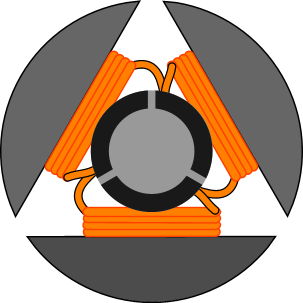
All electromagnets are winded with the same direction of rotation. Now, we have to distinguish two different situations as the motor rotates, The first situation, is when a brush is between two collectors. At this moment, all collectors are having power. During this time, one coil will have the same polarity between its poles, thus, this coil will NOT produce a magnetic a field as no current flows within.
The other situation is when one commutator piece has no power. This happens most of the time during the rotation of the motor. This commutator piece will act as a bridge for the two coils, that have one wire connected on it. Thus, these two coils will be considered as connected in series! And because their windings -as said before- have the same direction, they will both produce a magnetic field of the same magnetic polarity. The following two images indicates these two situations.
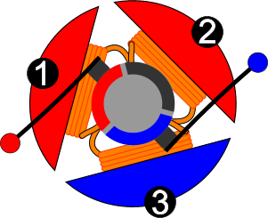 |  |
| The piece of commutator that is black has no power. It acts like a bridge for coils 1 and 2. These coils are connected in series and they generate the same magnetic polarity. | All commutators have power. This time, coil 2 has both its ends to the same electric polarity - NEGATIVE. Thus, coil 2 will produce no magnetic field at all. |
Finally, let's see a real motor hos it is made!
I always like tearing things apart and see how they work!
 |  |  |
| The victim | An exploded view of a DC motor. You can see the stator the rotor and the cover | Inside the stator you can see the two permanent magnets, one opposite the other. |
 |  |  |
| A close look on the rotor. The 3 electromagnets (armature) can be seen. Also, you can see the commutator, and -if you look close enough- you will see the gap between the contacts of the commutator. | This is the cover from the inside. The brushes are fixed on the cover. The spring-action metal along with the brushes are visible. On the other side of each metal there is the power contacts of the motor. They go out of the cover | Look close enough and you will see how the brushes are pushed against the commutator contacts. |
No comments:
Post a Comment